- Radars
- Aids to navigation

Features
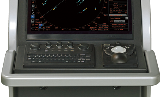
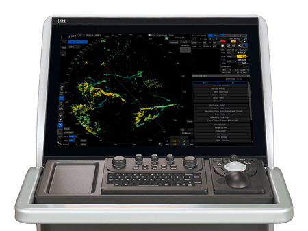
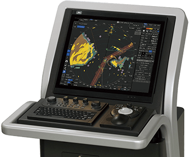
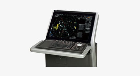
The JMR-9200/7200 series is a MED-certified marine radar incorporating a 26-inch-wide, 19-inch LCD and meeting the latest IMO performance standards. Incorporating a new Icon-based user interface to provide the latest functions in a user-friendly manner.
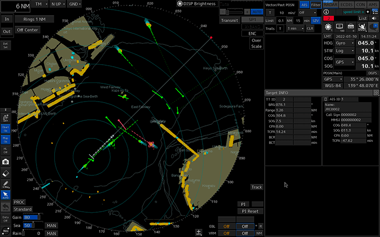
Sophisticated user interface
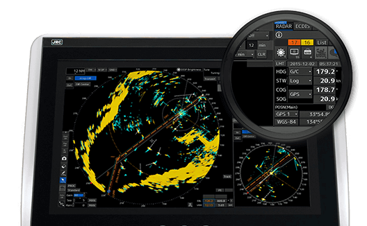
The JMR-9200/7200 series incorporates a new user interface (named jGUI) for an intuitive, easy-to-use, simple menu system based on the display of icons. This interface always displays critical data in fixed positions on the screen while icon-based menu display informs users of corresponding functions straightaway. Furthermore, target tracking (TT) and AIS symbols feature a pop-up displays while mouseover on the target showing their main data at a glance.
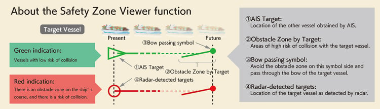
Safety Zone Viewer function [Update support available]*1
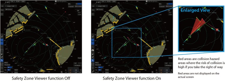
By displaying areas of high collision risk on the radar screen, navigators can intuitively grasp safe navigation areas. It is also effective in planning a course of avoidance in congested waters, as the safe
course can be seen at a glance. Even if you are already using the JMR-9200/7200 series, you can install
the Safety Zone Viewer by updating the software.
*1: Option
Safety Zone Viewer example of screen display
Safety Zone Viewer screen comparison
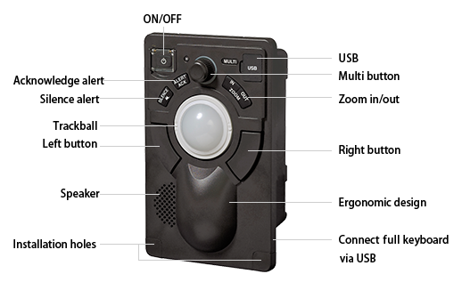
Easy-to-use operating unit
The newly designed trackball supports all the operation of the equipment. Users will be alerted with alarms from the operating unit and color changes under situations that require attention. The radar incorporates dedicated function buttons and control knobs similar to those of conventional models. Furthermore, the radar will be operable like conventional models by connecting an optional operating unit that incorporates a full keyboard.
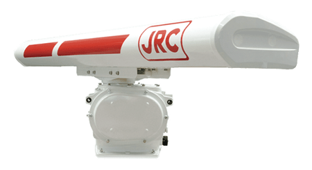
Solid-state scanner antenna
The JMR-9200/7200 series have been prepared X-band and S-band solid-state scanners. Each model incorporates a built-in performance monitor and has MED certification. The new S-band radar is the world's first MED-certified compact and lightweight model with an 8-ft solid-state scanner antenna following JRC's model with a 12-ft solid-state S-band scanner antenna. JRC's 8-ft series models include its first solid-state scanner antenna that rotates at the rate of as high as 48 rpm. This model using a scanner antenna with a weight of 90 kg is suitable for high-speed craft that needs to grasp situation changes quickly. A solid-state scanner antenna has the following advantages.
- No preheating or tuning required
No preheating or tuning is required. A stable image will be obtained promptly after the power is turned on. - A built-in Doppler filter clearly extracts target objects
Conventional magnetron radars have difficulty in using Doppler filters. A new digital signal processing method has made improvements in target detection performance in clutters. - Magnetron replacement unnecessary
The product adopted a highly reliable solid-state transmission circuit, thus eliminating periodical magnetron replacement and leading to a maintenance cost reduction.

6-ft Scanner

9-ft Scanner
X-band Solid-state Scanner
Example of 6-ft Solid-state Scanner Screen Display
S-band Solid-state Scanner
JRC's new processor brings advanced usability
The JMR-9200/7200 series incorporates JRC's newly developed high-speed processor. The outstanding processing capability has achieved optimum signal processing according to the distance from the own ship. This has greatly improved the target detection performance of the radar in short-distant sea clutter (reflection from the waves). With the target tracking (TT) function of the radar operated in the background continuously, the movement vector of a target object and numerical information on the object can be displayed immediately after the user acquires the target.
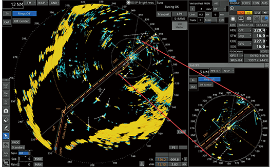
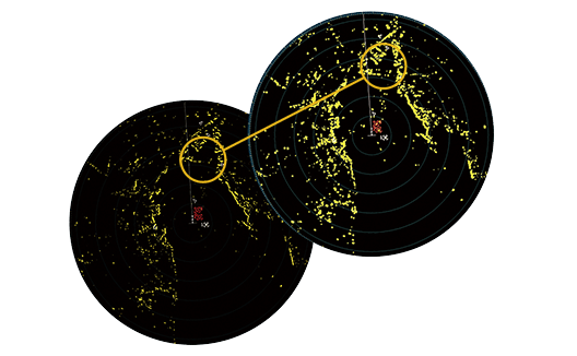
Furthermore, the JMR-9200 series with a 26-inch-wide screen makes it possible to use a second plan position indicator (PPI) in addition to the main PPI. While displaying two PPI's, it is possible to differentiate in range and off-center settings enabling the second PPI to expand a partial image around the own ship displayed in the main PPI and simultaneously monitor an area outside displayed on the main PPI.
Unique radar functions inherited
The JMR-9200/7200 series incorporates the unique features of JRC's radars that have been receiving a favorable reputation over the last decade.
Constaview(Real-time head-up function)
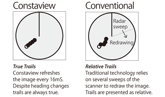
The patented Constaview is realized through the use of two in-house built high-speed processors. All information gathered by the radar is fully processed within a few milliseconds before being displayed, generating a smooth image rotation. Even changing azimuth mode, the radar image is displayed without any delay caused by the scanner rotation.
TEF (Target enhancement function)
Developed exclusively by JRC, TEF allows target enhancement relative to the target size. TEF works by adding pixels to targets displayed on the radar image and allows a vastly improved degree of discrimination between targets. Sophisticated processing results in a proportional enhancement where the relative enhancement of smaller targets is greater than applied to larger targets.
Function
Functional expansion
The equipment incorporates a variety of optional functions that will be available with software licenses added. Software licenses can be added before or after the radar comes into operation. Therefore, the radar can be customized to match the actual operating conditions.
Optional functions
- Chart radar function*2
- Safety Zone Viewer function*3
- Wave analysis function
- Expansion of AIS display targets (500 → 1000)
*2 : The chart radar function requires ENC cell permits as well as ECDIS.
*3 : Supported by software after by June 2022.
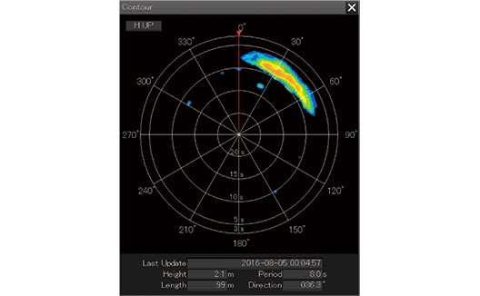
Wave analysis supports safe and fuel-efficient voyages
Sea surface reflection signals obtained around the own ship by the X-band radar are analyzed to display wave height, wave direction, wavelength, and wave cycle information along with spectrum images*4. The ship can take a course on the basis of information obtained from the wave analysis and suppress the pitching and rolling of the ship caused by waves, thus making it possible to ensure the safety of the crew members and cargo while saving the fuel consumption.
*4: The spectrum image is available to JMR-9200 series only.
VHF remote operation by radar
The radar offers a VHF remote operation function*5. This can be used to configure channels on the VHF unit or to perform DSC calls using AIS targets on the radar PPI screen. Features such as the wireless speaker mic*6 make it possible to communicate with other ships even when away from the VHF equipment.
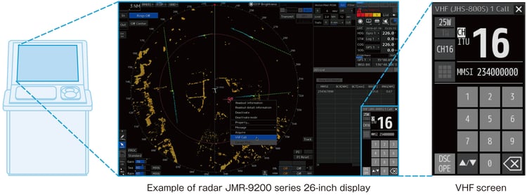
*5 : The VHF supports the JHS-800S.
*6 : Wireless speaker mic is option for the JHS-800S.
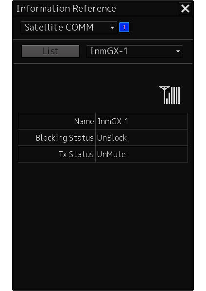
Satellite transmission blocking area display*7
During communications between JRC INMARSAT FBB or INMARSAT GX*8 equipment and satellites, the JMR-9200/7200 series equipment can display satellite antenna reception levels, blocking conditions, and transmission suspension*9.
*7 : Satellite transmission blocking area display is option, contact your JRC representative.
*8 : The INMARSAT FBB and INMARSAT GX support the JUE-251/501 and the JUE-60GX.
*9 : Transmission suspension supports only the JUE-60GX.
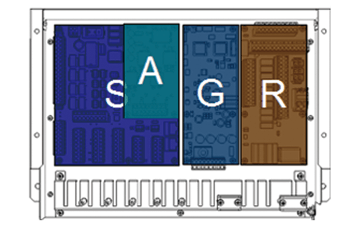
Interface circuit arrangement
in NQE-1143 Junction Box
Sensor data sharing
The Central Control Unit is provided with the minimum required external interfaces specified by Marine Equipment Directives (MEDs), and other sensor data is received through the bridge network (LAN) from the interface circuits. The interface circuits are designed to be shared by a number of new-type navigation devices, and each type of interface circuit can be combined and selected according to each signal format and the number of connections.
| SLC | AOC | GIF | RIF |
|---|---|---|---|
| ✓ | |||
| ✓ | ✓ | ||
| ✓ | ✓ | ||
| ✓ | ✓ | ✓ | |
| ✓ | ✓ | ✓ | |
| ✓ | ✓ | ✓ | ✓ |
Interface circuits in combination(Please refer to Block diagram)
Block diagram
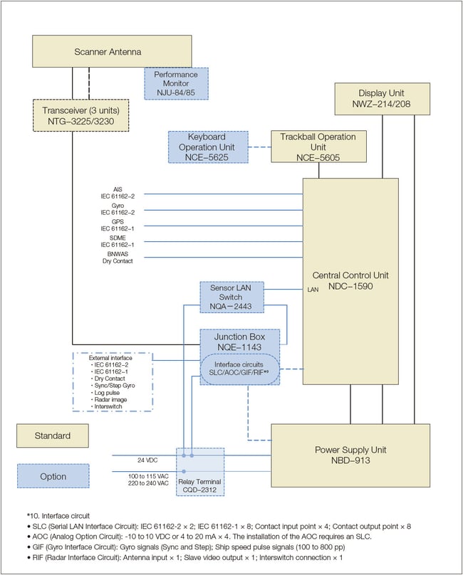
In the box
- Central Control Unit
- Power Supply Unit
- Display Unit
- Trackball Operation Unit
- Scanner Antenna
- Transceiver (in the case of 3-unit antenna)
Options
- Keyboard Operation Unit
- Sensor LAN Switch
- Junction Box
- Serial LAN Interface Circuit
- Analog Option Circuit
- Gyro Interface Circuits
- Radar Interface Circuit
- Relay Terminal Block
- Display Unit Mount Kit
- Performance Monitor (applicable to some scanner antennas)
- Interswitch (4 ch/8 ch)
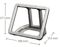
Dimensions
19-inch Display and Desktop Frame
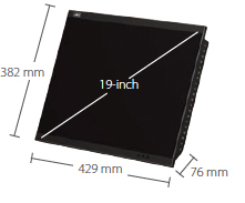
NWZ-214 Mass : 4.6 kg
CWB-1594*11 Mass : 3.6 kg
26-inch Display and Desktop Frame
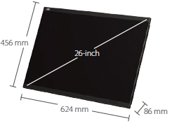
NWZ-208 Mass : 16 kg
CWB-1595*11 Mass : 5.5 kg
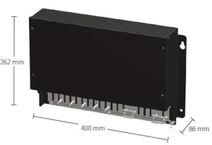
Central Control Unit
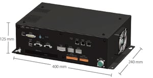
NDC-1590 Mass : 5.6 kg
Power Supply Unit
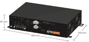
NBD-913 Mass:4.2 kg
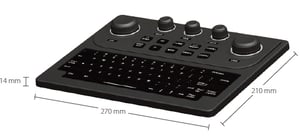
Trackball Operation Unit
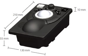
NCE-5605 Mass : 1.3 kg
Keyboard Operation Unit
NCE-5625*11 Mass : 0.8 kg
Junction Box
NQE-1143*11 Mass : 3.8 kg
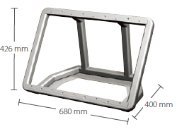
19-inch Cradle Frame and 26-inch Cradle Frame
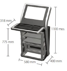
CWA-245*11 Mass : 55 kg
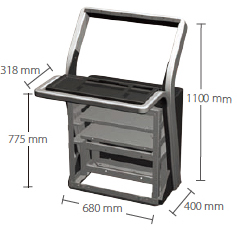
CWA-246*11 Mass : 65 kg
10-kW 6 ft X-band Scanner Antenna (2 units)

NKE-2103-6*12 (27 rpm)/NKE-2103-6HS*12 (48 rpm) Mass : 40 kg
25-kW 6 ft X-band Scanner Antenna (2 units)

NKE-1125-6*12 (24 rpm)/NKE-2254-6HS*12 (48 rpm) Mass : 55 kg
25-kW 9 ft X-band Scanner Antenna (2 units)

NKE-1125-9*12 (24 rpm) Mass : 60 kg
25-kW 7 ft X-band Scanner Antenna (3 units*13)

NKE-1129-7*12 (24 rpm) Mass : 51 kg
25-kW 9 ft X-band Scanner Antenna (3 units*13)

NKE-1129-9*12 (24 rpm) Mass : 53 kg
30-kW 12 ft S-band Scanner Antenna (2 units)

NKE-1130*12 (24 rpm) Mass : 180 kg
30-kW 12 ft S-band Scanner Antenna (3 units*13)

NKE-1139*12 (24 rpm) Mass : 165 kg
600 W 6 ft X-band Solid-state Scanner Antenna (2 units)

NKE-1696-6 (24 rpm) Mass : 53kg
600 W 9 ft X-band Solid-state Scanner Antenna (2 units)

NKE-1696-9 (24 rpm) Mass : 58kg
250 W 8 ft S-band Solid-state Scanner Antenna (2 units)

NKE-2632 (24 rpm) Mass : 85 kg
250 W 8 ft S-band Solid-state Scanner Antenna (2 units)
NKE-2632-H (48 rpm) Mass : 90 kg
250 W 12 ft S-band Solid-state Scanner Antenna (2 units)

NKE-1632 (24 rpm) Mass : 160 kg
*11 : Option.
*12 : The performance monitor is option.
*13 : The transceiver NTG-3225 is required.
Specifications
| Model | 26-inch type*14 | JMR-9210-6X JMR-9210-6XH |
JMR-9225-6X JMR-9225-9X |
JMR-9225-6XH | JMR-9225-7X3 JMR-9225-9X3 |
JMR-9230-S | JMR-9230-S3 | JMR-9282-S JMR-9282-SH |
JMR-9272-S | JMR-9296-6X JMR-9296-9X |
|
|---|---|---|---|---|---|---|---|---|---|---|---|
| 19-inch type*14 | JMR-7210-6X JMR-7210-6XH |
JMR-7225-6X JMR-7225-9X |
JMR-7225-6XH | JMR-7225-7X3 JMR-7225-9X3 |
JMR-7230-S | JMR-7230-S3 | JMR-7282-S JMR-7282-SH |
JMR-7272-S | JMR-7296-6X JMR-7296-9X |
||
| Conforming to IMO standards | ✓ | ✓ | ✓ | ✓ | ✓ | ✓ | ✓ | ✓ | ✓ | ✓ | |
| Unit configuration | 2-unit | 3-unit *15 |
2-unit | 3-unit *16 |
2-unit | ||||||
| Performance Monitor | NJU-85 | NJU-84 | Built-in | ||||||||
| Frequency | X-band | S-band | X-band | ||||||||
| Display | Color raster scan PPI | ||||||||||
| Scanners | |||||||||||
| Model*14 | NKE-2103-6 NKE-2103-6HS |
NKE-1125-6 NKE-1125-9 |
NKE-2254-6HS | NKE-1129-7 NKE-1129-9 |
NKE-1130 | NKE-1139 | NKE-2632 NKE-2632-H | NKE-1632 | NKE-1696-6 NKE-1696-9 |
||
| Antenna length | 6 feet | 6/9 feet | 6 feet | 7/9 feet | 12 feet | 8 feet | 12 feet | 6 / 9 feet | |||
| Transmission output | 10 kW | 25 kW | 30 kW | 250 W (solidification) | 600 W (solidification) |
||||||
| Transmission frequency | 9410 MHz ± 30 MHz | 3050 MHz ± 20 MHz | P0N:3035 MHz Q0N:3065±4 MHz or 3060±4 MHz |
P0N:9410 MHz Q0N:9440±4 MHz or 9435±4 MHz |
|||||||
| Horizontal beam width | 1.2 ° | 6 feet:1.2 ° 9 feet:0.8 ° |
1.2 ° | 7 feet:1.0 ° 9 feet:0.8 ° |
1.9 ° | 2.7 ° | 1.9 ° | 1.2 ° | 0.8 ° | ||
| Vertical beam width | 20 ° | 25 ° | 25 ° | 20 ° | |||||||
| Rotational speed | 27 rpm 48 rpm (high-speed rotation) |
24 rpm | 48 rpm (high-speed rotation) |
24 rpm | 24 rpm | 24 rpm 48 rpm (high-speed rotation) |
24 rpm | 24 rpm | |||
| Pulse width/ Frequency*17 |
0.08 µs/ 2250 Hz |
0.07 µs/2250 Hz,0.2 µs/2250 Hz | 0.07 µs/(4.6 µs, 8 MHz)/1860 Hz or 2280 Hz |
0.07 µs/(4.6 µs, 8 MHz)/1360 Hz or 1700 Hz |
|||||||
| 0.25 µs/ 1700 Hz |
0.3 µs/1900 Hz,0.4 µs/1400 Hz | 0.14 µs/(9.1 µs, 8 MHz)/1860 Hz or 2280 Hz |
0.14 µs/(9.1 µs, 8 MHz)/1360 Hz or 1700 Hz |
||||||||
| 0.5 µs/ 1200 Hz |
0.8 µs/750 Hz | 0.29 µs/(9.1 µs, 8 MHz)/1860 Hz or 2280 Hz |
0.28 µs/(9.1 µs, 8 MHz)/1000 Hz |
||||||||
| 0.8 µs/750 Hz | 1.0 µs/650 Hz | 0.57 µs/(9.1 µs, 8 MHz)/1280 Hz | 0.56 µs/(9.1 µs, 8 MHz)/1000 Hz | ||||||||
| 1.0 µs/650 Hz | 1.2 µs/510 Hz | 1.14 µs/(18.3 µs, 8 MHz)/640 Hz | 1.12 µs/(18.3 µs, 8 MHz)/660 Hz or 730 Hz | ||||||||
| Duplexer | Circulator + Diode limiter | Circulator +TRHPL |
Circulator + Diode limiter | ||||||||
| Range scale | 0.125, 0.25, 0.5, 0.75, 1.5, 3, 6, 12, 24, 48, 96 NM | ||||||||||
| Motor | Brushless | ||||||||||
| Tuning | Auto/Manual | ||||||||||
| Ambient conditions | Temperature: -25 to 55 °C (NTG-3225/NTG-3230: -15 °C to 55 °C); Relative humidity: 93 % @40 °C | ||||||||||
| Display unit | |||||||||||
| LCD | JMR-9200: 26-inch WUXGA color LCD, 1920 × 1200 dots JMR-7200: 19-inch SXGA color LCD, 1280 × 1024 dots |
||||||||||
| PPI effective diameter | JMR-9200: 320 mm min. JMR-7200: 250 mm min. |
||||||||||
| Azimuth display mode | North up, course up, and head up | ||||||||||
| Operation mode | Relative motion - True trails; Relative motion - Relative rails; True movement - True rails | ||||||||||
| EBL | Two (EBL1/EBL2), (Center/Independent), 000.0 to 359.9 °, Four-digit display | ||||||||||
| VRM | Two (VRM1/VRM2), 0.000 to 96.0 NM, Four-digit display | ||||||||||
| Sea surface/Rain and snow reflection suppression |
Auto/Manual | ||||||||||
| Trail display | Short (off,15 s to 60 mins.)/Long (off,30 mins to 24 hrs.), Two modes | ||||||||||
| Own ship trail records | 24 hours | ||||||||||
| User map | 100,000 points | ||||||||||
| Off-center | 66 % of the radius (excluding 96 NM range) | ||||||||||
| Number of TT tracking targets | 100 max. | ||||||||||
| TT tracking range | Auto/Manual 32 NM max. | ||||||||||
| Number of AIS targets | 500 targets max. (expanding to a maximum 1,000 targets with an optional function added) | ||||||||||
| TT/AIS vector | True/Relative, variable from 1 to 120 minutes | ||||||||||
| Ambient conditions | Operating temperature: -15 °C to 55 °C; Relative humidity: 93 % @40 °C | ||||||||||
| Power supply voltage | 100-115 V AC, 50/60 Hz,1 φ/220-240 V AC, 50/60 Hz,1 φ/24 V DC | ||||||||||
| Option | |||||||||||
| Chart radar function | Software license | ||||||||||
| Expansion of number of AIS display targets | Software license | ||||||||||
| Wave analysis function | Software license | ||||||||||
| Keyboard Operation Unit | NCE-5625 | ||||||||||
| Junction Box | NQE-1143 | ||||||||||
| Interface Circuits | CMH-2370(Serial LAN Interface Circuit)/CMJ-560(Analog Option Circuit)/CMJ-554(Gyro Interface Circuit) | ||||||||||
| Self-stand Frame | CWA-245 (19 inches) /CWA-246 (26 inches) | ||||||||||
| Power Control Unit | NQE-3167 | ||||||||||
| Interswitch | NQE-3141-4A (box, up to 4 units) | ||||||||||
| Interswitch | NQE-3141-8A (box, up to 8 units) | ||||||||||
| Anti-icing Antenna*18 | None | NKE-1125-6D/9D | NKE-2254-6HSD | NKE-1129-7D/9D | NKE-1130D | NKE-1139D | NKE-2632 D/E |
NKE-1632 D/E |
NKE-1696D/E | ||
*14 : Each model with the model number suffi x “H” is a high-speed rotation model.
*15 : External Transceiver: NTG-3225
*16 : External Transceiver: NTG-3230
*17 : The NKE-2632/1632 scanner antennas: Transmission pulse width (1st)/(Transmission pulse width and frequency shift width (2nd))/Repetition frequency
*18 : The supply voltage of each model is shown by the suffix. D: 100 VAC and E: 220 VAC
Product Inquiry

Product Inquiry

