- Security and Surveillance - VTS
- Fishery Coordination Solution - VTS
- Marine Surveillance - VTS
- Port Surveillance - VTS
Features

About "TRIHAWK V650series"
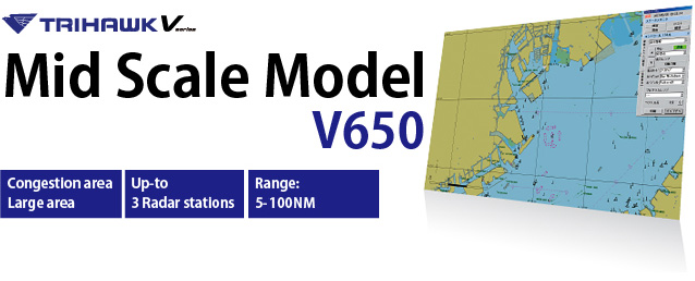
The "TRIHAWK V650 Series" is the JRC standard type of VTS system capable of a medium to large scale of sea area surveillance. This system can integrate the data from 3 radar stations to monitor vessel movements in a wide sea area (100NM). This series can be designed for the Basic and Standard System in accordance with IALA-128.
V650 Series Features
- Multi-radar integration of up to 3 radar stations
- Medium to large scale of VTS system configuration
- Various types of radar antenna selectable
- Solid-state X-band radar available
- Linking with CCTV camera (option)
- Complied with IALA V-128 Basic and Standard
- Complied with IMO Resolution A.857(20)
About VTS
The purpose of vessel traffic service is to improve the safety and efficiency of vessel traffic and to protect the environment.
One of the main functions to attain the purpose of VTS is the function of monitoring vessel movements, by which the positions and movements of a number of vessels navigating in the water areas within the multi-radar coverage can be monitored and presented on an electronic chart display screen. Using this function, the VTS operator can transmit proper messages to each vessel and accurate information to various organizations related to ports and routes.
For instance, if a vessel is sailing toward a shallow water area, the operator can foresee a risk of grounding in monitoring the VTS screen. In this case, the VTS operator can call to the vessel via the international VHF communication system (as he can recognize the vessel's name by AIS) and advise the vessel of its risk of grounding by allowing the vessel to have a chance of turning the rudder to avoid the danger of grounding. Thus, the potential impact of such grounding on the sea environment and a resulting economic loss can be prevented. In addition to such risk of grounding, the VTMS allows various alert operations to prevent vessels from various risks such as collisions of vessels, intrusion into a restricted water area, and intrusion of a suspected vessel to a guarded area.
Functions
V650 Series Functions
Multi-radar Integration
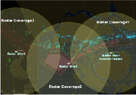
The radar information from up to 3 radar stations can be integrated and tracked on the VTS screen. This function allows the seamless surveillance of a wider sea area. A shadow area which a single radar station cannot detect can also be monitored by the multi-radar integrated system.
Various Types of Antenna
Each radar antenna is selectable from a lineup of 9-foot (2-unit), 9-foot (3-unit), 18-foot (3-unit) horizontal and 18-foot(3-unit) circular types, and the X-band transmitter/ receiver system is available in the conventional magnetron type and the solid-state type, allowing the optimum system configuration to meet the purpose of use and the sea water coverage.

Solid State Transmitter Receiver (NTG-403)

18ft Antenna

9ft Antenna
Automatic Radar Tracking
The Image Server/Tracker provides high resolution radar image processing and high tracking performance. The tracking of the target echo entering in the pre-set area or crossing the line setting by the user on the Operation Display is automatically started and the tracking of only selected target echo(es) by manual is (are) also available. The stationed buoy or rocks such as not expecting vessel are able to exclude a tracking target.
Alarm Function
This VTS system is provided with various alarm functions to prevent vessel collision accidents and keep the safety and security at sea areas.
If pre-setting alarm conditions are satisfied, the alarm sound is automatically generated and inform to the operator. Pre-setting alarms are as follows;
- Guard Zone Entry (drawn by operator)
- Guard Line Crossing
- Speed Limit (maximum speed, minimum speed)
- Leaving Anchor
- CPA/TCPA
- Lost Target
- System Failure, etc.
Recording and Playback Function
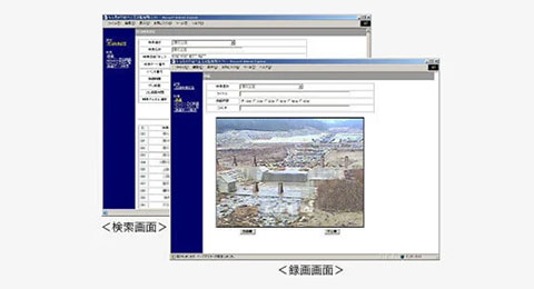
The information on the Operation Display and tracking target in formation are automatically recorded (recording period can be selected by the user) and are able to replay on the Operation Display with a playback software. Automatic recording is functioned during the playback operation simultaneously.
This function allows the status analysis to be made in event of accident occurrence and the sea area management system to be improved.
AIS Receiver (option) / AIS Base station(option)
AIS information can be integrated on the Operation Display. If the radar target echo and the AIS target vessel are identified, those are automatically integrated and displayed on the screen with a single symbol.
The VTS system can select the function of AIS base Station and send own station data to other stations.
CCTV Camera (option)
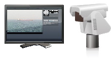
By integrating the radar system with a CCTV (closed circuit television) camera, the system can control the camera to direct to a target echo on the radar monitor of the Operation Display. The system can also control the CCTV camera to track a target echo based on the radar track information or to automatically track a vessel which enters a security area. Therefore, the actual movement of the vessel can be monitored on the CCTV monitor using the symbol indicated on the radar monitor.
Operation Display
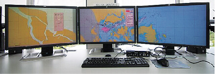
Up to 5 Operation Displays can be installed optionally, allowing two or more VTS operators to monitor sea water areas. By selecting optional displays, up to 3 screens ca n be connected to one Operation Display Unit. The 3 display screens can present 3 different displays individually or one integrated water area as a single screen, allowing flexible screen configuration.
Network selection (option)
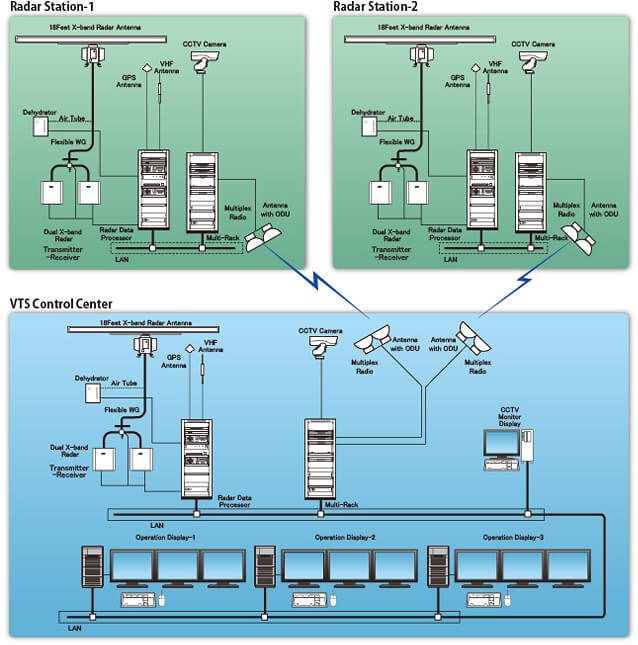
The network linking multiple radar stations and the surveillance center with each other can select LAN connection and the following types of link:
- Wireless LAN
- Optical fiber cable
- Microwave multiple
System
V650 Series Selection Guide
BASE KIT
| 9ft 2unit | 9ft 3unit | 18ft 3unit | |||
|---|---|---|---|---|---|
| Radar Antenna |
Horizontal |
Horizontal |
Horizontal/ |
||
| Transmitter Receiver |
SS |
25kW |
SS |
25kW |
|
Radar Data Processor

Operation Display
OPTIONAL KIT

Additional Operation Display
Up to four Additional Operation Display

Additional Display
Up to two Additional Display per one PC

Dehydrator
CCTV Camera Kit

Multi CCTV
Rack Camera
Camera Set
Up to one Camera per one station

CCTV Monitor Display

Digital Recorder
AIS Base Station Kit

VHF Antenna

GPS Antenna

AIS Transponder (install in RDP rack)
AIS Receiver Kit

AIS Receiver

AIS Interface (install in RDP rack)

Serial-IP Converter (install in RDP rack)
NETWORK SELECTION SAMPLE

Optical fiber Cable

Wireless LAN

Microwave network
V650 Series System Configuration
Display
Display Examples
Entrance Of Tokyo Bay
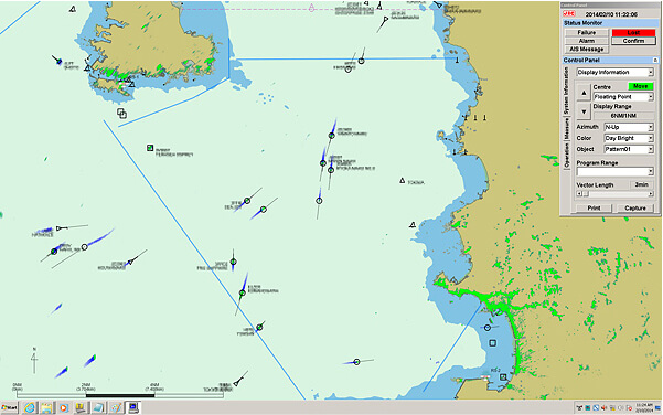
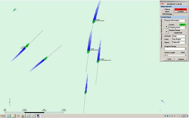
Target ZoomUP
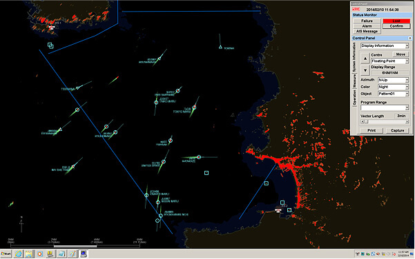
NightMode
Specs
V650 Series Specifications
| Model | V650 Series | |||
|---|---|---|---|---|
| Radar Antenna | NKE-326,330 | NKE-339,336 | NKE- 351,352,353,354, 355,356 |
|
| Antenna length | 9ft 2unit | 9ft 3unit | 18ft 3unit | |
| Transmitting power | 25kW | 25kW/SS*1 | 25kW/SS*1 | |
| Rotation speed | 24rpm | 22rpm | ||
| Polarization | Horizontal | Horizontal(NKE-353,354,355,356) /Circular(NKE-351,352) |
||
| Frequency | 9410(NKE-326,339)/9740MHz(NKE-330,336) | 9375(NKE-351,352,353,354) /9740MHz(NKE-355,356) |
||
| Dimension Swing Circle x Height / Weight |
2825 x 536 mm/ 60kg | 2825 x 536 mm/ 53kg | 5330 x 634 mm/ 110kg | |
| Installation cable | 30/50/100m (between Processor and Scanners) | |||
| Environment | Temperature: -25 to +55°C, Relative humidity: 93% at +40°C | |||
| Radar Data Processor | NCE-5548 Max 3 radar composition | |||
| Input Signal | radar video signal, antenna bearing signal, trigger signal | |||
| Video adjustment Function | anti sea clutter, scan correlation, sweep integration, anti rain clutter, interference rejects | |||
| Alarm Function | warning line & area alarm, anchor watch,high/low speed, CPA/TCPA | |||
| Automatic Tracking | Max 300 targets per station | |||
| LAN interface | Ethernet 10/100BASE-TX | |||
| Power Supply | AC100/110/120/220/230/240V | |||
| Power consumption | 2kVA or less | |||
| Dimension (W)x(D)x(H)/Weight | 600 x 700 x 1900mm/ 250kg or less | |||
| Operation Display | NCD-2246 | |||
| OS | Windows7 professional 32bit | |||
| Memory | 4GB | |||
| LAN interface | Ethernet 10/100BASE-TX | |||
| Presentation | radar video image, radar tracked data, alarm data, electronic chart, range mark, bearing scale, L/L line, EBL/VRM, radar control window, AIS target data(*1) etc |
|||
| Electronic Chart | ENC S63 support (Option) | |||
| Record Period | 31 days | |||
| Record Interval | Selectable (10, 30, 60, 90, 120 seconds) | |||
| LCD | 1920 x 1200 pixel(WUXGA) | |||
| Optional items | ||||
| Dehydrator | NZA-283 | |||
| AIS Receiver kit | NZA-288 Max 1000 targets | |||
| AIS Receiver | NTE-182BR | |||
| AIS Interface | NCX-4282 | |||
| Serial IP Converter | CMH-2354 | |||
| AIS Base Station kit | NZA-287 Max 1000 targets | |||
| AIS Transponder | JHF-307 | |||
| VHF Antenna | SL-150 | |||
| GPS Antenna | CCAH32ST14 | |||
| Additional Operation Display | NCD-2246 Max 4 Additional Operation Display | |||
| Additional Display | NWZ-204 Max 2 Additional Displays per Operation Display | |||
| CCTV Camera kit | NZA-284 | |||
| Camera Station kit | Max 1 Camera Station per station CCTV Camera system with Multi Rack |
|||
| CCTV Monitor Display | Max 1 CCTV Monitor Display per system | |||
| Digital Recorder | Max 1 Digital Recorder per system | |||
| Others | ||||
| Network | The network linking from site to site are optionally available. The following network types are selectable:
|
|||
| Others | The others, it must be option sales such as a equipment foundation for the installation. | |||
*1 SS: Solid State 200W
- All specifications are subject to change without notification
Related Products
Security and Surveillance
Fishery Coordination Solution
Marine Surveillance
Port Surveillance
- VTS
Discontinued Products
Please note that some of the contents may have been changed or are no longer available.Please be aware of this in advance.


