- Land system
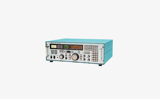
The NRD-730 is a short to medium-wave receiver developed with cutting-edge digital technologies, which can be used for coast, land and marine stations.
- Software radio with high-performance SoC
(System on Chip) - LAN interface implementation

Features
Software Defined Radio (SDR)
The receiver has realized a programmable SDR by using a high-performance system control chip (SoC), in which a software-programmable processor and a hardware-programmable FPGA are implemented in a single chip component.
In the future, the software can be updated to meet the communication specifications required for the latest GMDSS.
High-performance analog-to-digital converter (ADC)
High-speed, high-resolution, high-performance ADCs are used to achieve high dynamic range characteristics and excellent effective selection performance.
Noise reduction function
By employing an adaptive noise canceller using digital signal processing, only the desired speech signal is extracted from the received speech that contains noise components, enabling clearer listening.
Built-in DSC demodulation function
Built-in DSC demodulation function specified by GMDSS*.
* The demodulated DSC can be checked by an external device using a LAN interface.
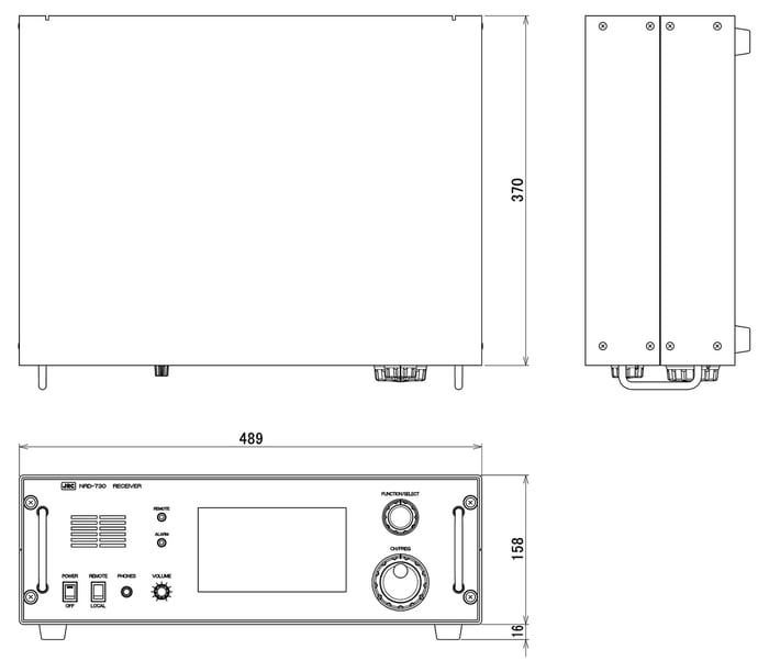
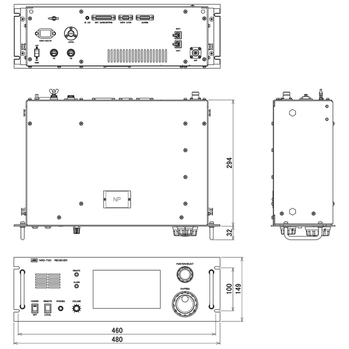
Dimensions
Desktop type

Rack mount type

Specification
| Frequency Range | 90 kHz to 29.999999 MHz (1 Hz steps) | ||
|---|---|---|---|
| Receiving System | Direct RF Sampling System | ||
| Modes | CW(A1a), MCW(A2A、H2A), DSB(A3E), USB/LSB(R3E, H3E, J3E, J2D), FSK(F1B, J2B), FAX(F3C), ISB(B8E, B9W) | ||
| Number of Preset Channels | 300 channels (frequency, mode, bandwidth, AGC and ATT) | ||
| Receiving Sensitivity | Frequency : 90 kHz to 1599.999 kHz | CW mode:10 μV or less DSB mode:30 μV or less |
|
| Frequency : 1600 kHz to 29.999999 MHz | CW mode:2 μV or less DSB mode:6 μV or less SSB mode:3 μV or less |
||
| Bandwidth: 3 kHz; output: 100 mW CW: (S+N) / N = 20 dB DSB: (S+N) / N = 20 dB, 1 kHz, 30 % modulation SSB: (S+N+D) / (N+D) = 20 dB |
|||
| Signal Selectivity | Bandwidth 6 kHz | Attenuation: 6-dB bandwidth 4.5 kHz to 7.0 kHz 60-dB bandwidth 14 kHz or less |
|
| Bandwidth 3 kHz | Attenuation: 6-dB bandwidth 2.7 kHz to 3.3 kHz 60-dB bandwidth 4.4 kHz or less |
||
| Bandwidth 2.7 kHz | Attenuation: 6-dB bandwidth 2.4 kHz to 3.0 kHz 60-dB bandwidth 4.1 kHz or less |
||
| Bandwidth 1 kHz | Attenuation: 6-dB bandwidth 1.0 kHz to 1.5 kHz 60-dB bandwidth 3.0 kHz or less |
||
| Bandwidth 0.5 kHz | Attenuation: 6-dB bandwidth 0.45 kHz to 0.6 kHz 60-dB bandwidth 2.0 kHz or less |
||
| Bandwidth 0.3 kHz | Attenuation: 6-dB bandwidth 0.27 kHz to 0.3 kHz 60-dB bandwidth 1.1 kHz or less |
||
| Frequency Stability | Within ±10 Hz from 1 min after startup | ||
| Spurious Response | Image rejection ratio: 70 dB or more IF rejection ratio: 80 dB or more |
||
| Effective selectivity | J3E (Radio Telephone) When an unwanted signal at a spacing of more than 4 kHz from the desired signal is applied to the desired signal input voltage of 10 μV, the unwanted signal input voltage that suppresses the output of the desired signal by 3 dB is 10 mV or more F1B (DSC, NBDP) Character error rate less than 1 x 10⁻² Desired signal: Input level =10 μV Unwanted signal: input level = 1 mV, no modulation, steady-state deviation frequency = ±500 Hz |
||
| Overall Distortion Noise | Input voltage of 30 μV is applied, the ratio between the output at 1000 Hz and the unwanted component in the output at 500 mW of low frequency output is more than 20 dB. | ||
| AGC Characteristic | The variation of the low frequency output for the antenna input of 3 μV to 100 mV is 10 dB or less. | ||
| Conducted Spurious Emission | The power emitted from the antenna terminal is 4 nW or lower. | ||
| Nominal RF Input Impedance | 50 Ω unbalanced | ||
| High Frequency Attenuator | Approx. 20 dB / Approx. 10 dB | ||
| Auxiliary Functions | Scan, Sweep, Squelch, Noise Blanker, Self-diagnostics, AGC selection, PBS | ||
| PBS (Pass Band Shift) Variation | ±0.12 kHz (when selecting 0.3 kHz) | ||
| ±0.2 kHz (when selecting 0.5 kHz) | |||
| ±0.5 kHz (when selecting 1 kHz) | |||
| ±1.2 kHz (when selecting 2.7 kHz) | |||
| ±1.2 kHz (when selecting 3 kHz) | |||
| ±2.0 kHz (when selecting 6 kHz) | |||
| Variable Range of BFO and Clarifier | BFO: ±9.999 kHz (1 Hz step) Clarifier: ±200 Hz (1 Hz step) |
||
| Line Output | -20 dBm to +10 dBm (600 Ω balanced) | ||
| Remote Interfaces | RS-423A / Ethernet | ||
| Power Requirements | AC100 V to 240V (85 V to 264 V), Single-phase 50/60 Hz DC: +24 V (operable -25 % and +35 %) AC/DC automatic switchover (automatic switchover to DC power source when AC power source turns off) |
||
| Operation Conditions | Preheat time: 1 min Temperature range: between -15 °C and +55 °C Relative humidity: 90 % (at +35 °C, without condensation) |
||
| Dimensions | Desktop type: 158(H) x 489(W) x 370(D) mm Rack mount type: 149(H) x 480(W) x 294(D)mm |
||
| Weight | 6.0 kg Desktop enclosure: 4.0 kg |
||
特長
本EPIRBは、国際規格IEC 61097-2 Ed.4(2021年4月)に適合した動作・性能試験を実施しています。国土交通省の型式承認品のため、日本籍船への搭載が可能です。
通常のLEDライトと赤外線LEDライトの両方を内蔵し、夜間や暗闇でのSAR活動をより良くサポートすることができます。
欧州の全地球測位衛星システム Galileo のリターンリンクサービス(2020年1月より運用開始)に対応しています。
| 受信周波数範囲 | 90kHz ~ 29.999999MHz(1Hzステップ) | ||
|---|---|---|---|
| 受信方式 | ダイレクトRFサンプリング | ||
| 受信電波型式 | CW(A1a)、MCW(A2A、H2A)、DSB(A3E)、USB/LSB(R3E、H3E、J3E、J2D)、FSK(F1B、J2B)、FAX(F3C)、ISB(B8E、B9W) | ||
| プリセットチャネル | 300チャネル以上(受信周波数、受信モード、帯域幅、AGC、ATT) | ||
| 受信感度 | 周波数:90kHz ~ 1600kHz | CWモード:10μV以下、DSBモード:30μV以下 | |
| 周波数:1600kHz ~ 29.999999MHz | CWモード:2μV以下、DSBモード:6μV以下、SSBモード:3μV以下 | ||
| ただし、帯域幅:3kHz、出力:100mW CW:(S+N) / N = 20dB DSB:(S+N) / N = 20dB、1kHz、30%変調 SSB:(S+N+D) / (N+D) = 20dB | |||
| 信号選択度 | 帯域幅:6kHz | (減衰)6dB帯域幅:4.5 kHz~7.0 kHz、60dB帯域幅:14.0 kHz 以下 | |
| 帯域幅:3 kHz | (減衰)6dB帯域幅:2.7 kHz~3.3 kHz、60dB帯域幅:4.4 kHz 以下 | ||
| 帯域幅:2.7 kHz | (減衰)6dB帯域幅:2.4 kHz~3.0 kHz、60dB帯域幅:4.1 kHz 以下 | ||
| 帯域幅:1 kHz | (減衰)6dB帯域幅:1.0 kHz~1.5 kHz、60dB帯域幅:3.0 kHz 以下 | ||
| 帯域幅:0.5 kHz | (減衰)6dB帯域幅:0.45 kHz~0.6 kHz、60dB帯域幅:2.0 kHz 以下 | ||
| 帯域幅:0.3 kHz | (減衰)6dB帯域幅:0.27 kHz~0.3 kHz、60dB帯域幅:1.1 kHz 以下 | ||
| 周波数安定度 | 起動1分後から±10Hz以内 | ||
| スプリアスレスポンス | 影像妨害比:70dB 以上 中間周波数妨害比:80dB 以上 | ||
| 実効選択度 | J3E(無線電話) 10μVの希望周波数入力電圧を加えた状態で、希望波から4kHz離れた妨害波を加えた場合に おいて、希望波の出力を3dB抑圧する妨害波は10mV以上 F1B(DSC、NBDP) 文字誤り率は 1 x 10⁻² 以下 希望信号:入力レベル =10μV 不要信号:入力レベル =1mV、変調なし、定常偏差周波数 = ±500Hz | ||
| 総合歪み雑音 | 30μVの入力電圧を加えたときに、低周波出力500mWにおいて1000Hzの出力と、その中に含まれる不要成分との比が20dB以上 | ||
| AGC特性 | アンテナ入力3μVから100mVに対し低周波出力の変化は10dB以下 | ||
| 副次発射 | アンテナ端子から発射される電力は4nW以下 | ||
| 公称入力インピーダンス | 50Ω 不平衡 | ||
| 高周波減衰器 | 約 20 dB / 約 10 dB | ||
| 補助機能 | スキャン、スイープ、スケルチ、ノイズブランカ、自己診断、AGC選択、PBS | ||
| PBSの可変量 | 帯域幅 | 0.3KHz、0.5kHz、1kHz、2.7kHz、3kHz、6kHz | |
| 可変範囲 | +/- 0.12kHz、+/- 0.2kHz、+/- 0.5kHz、+/- 1.2kHz、+/- 1.2kHz、+/- 2.0kHz | ||
| BFO/クラリファイアの可変量 | BFO:+/- 9.999kHz (1Hz step) クラリファイア:+/- 200Hz (1Hz step) | ||
| ライン出力 | -20 dBm ~ +10 dBm(600Ω、平衡) | ||
| リモート I/F | RS-423A / Ethernet | ||
| 電源 | AC100~240V (85~264V)、単相 50/60Hz DC +24V (-25%~+35%) ACからDCへ自動切換 | ||
| 動作条件 | 余熱時間:1分 温度範囲:-15℃~+55℃ 相対湿度:90%(+35℃にて) | ||
| 外形寸法 | 卓上型:158(H)x 489(W)x 370(D)mm ラック型:149(H)x 480(W)x 294(D)mm | ||
| 質量 | 本体:約 6kg 卓上型筐体:約 4kg | ||


